Detailed assembly and construction instructions for building the ESCTL Door Controller board and associated components.
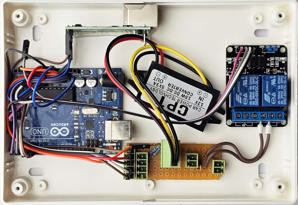 Inside of an assembled door node (missing the serial number label in this photo).
Construction Details
The wiring logic depends on whether you are building the Serial (RS232) or Ethernet version of the controller.
- Serial Version: Connect TX-TX and RX-RX between the RS232 driver and the Arduino.
- Ethernet Version: Connect TX-RX and RX-TX between the Ethernet driver and the Arduino.
The instructions below refer to the latest revision of the Ethernet version.
Suggested Wiring Order
We have found the table below to show a good order to complete the wiring between internal components (you may connect in any order, of course)
Refer to the Pinouts Reference for specific Arduino pin assignments (some are copied below for ease of reference, but the pinout page has the definitive documentation).
| Cable Type | From | To | Mapping |
|---|---|---|---|
| 5 x M-F | Lower 4 pins of 5-pin header on connection board, and voltage sense resistor | Arduino | vIn → VIn GND → GND Reader(D0)→3 Reader(D1)→4 Voltage_Sense→A3 |
| 3 x M-F | Ethernet module | Arduino | TX → RX RX → TX GND → GND |
| 1 x F-F | Top pin of 5-pin header on connection board | Arduino | 5V → Vdd |
| 1 x M-F | Ethernet | Arduino | CFG → (Not yet used) |
| 4 x F-F | Relay board | Arduino | GND → GND IN1 → A0 IN2 → (N/C) Vdd → Vdd Note: We use a 90-degree pin header to connect the F-F cable to A0, and use the ICSP header pins on the Arduino for GND and Vdd (5V). |
Connection Board
The connection board is constructed from Veroboard 01-3938 3.18mm pitch stripboard (RS order code 433-832), cut to 15x5 sections (earlier revisions used 12x5).
- Cable Lengths: Flying leads should be cut to 75mm, and bootlace ferrules used to connect to the relay.
- Voltage Sense:
- 4k7 resistor connected to GND.
- 15k resistor connected to Vin.
- Solder the other ends together and use one lead to connect to Arduino pin A3.
- Flyback Protection: Use a 1N4004 diode. The stripe (cathode) must be connected to V+(lock) and the other end to GND.
- Track Cut: One track needs to be cut, at the point indicated by the red “X” on the image below.
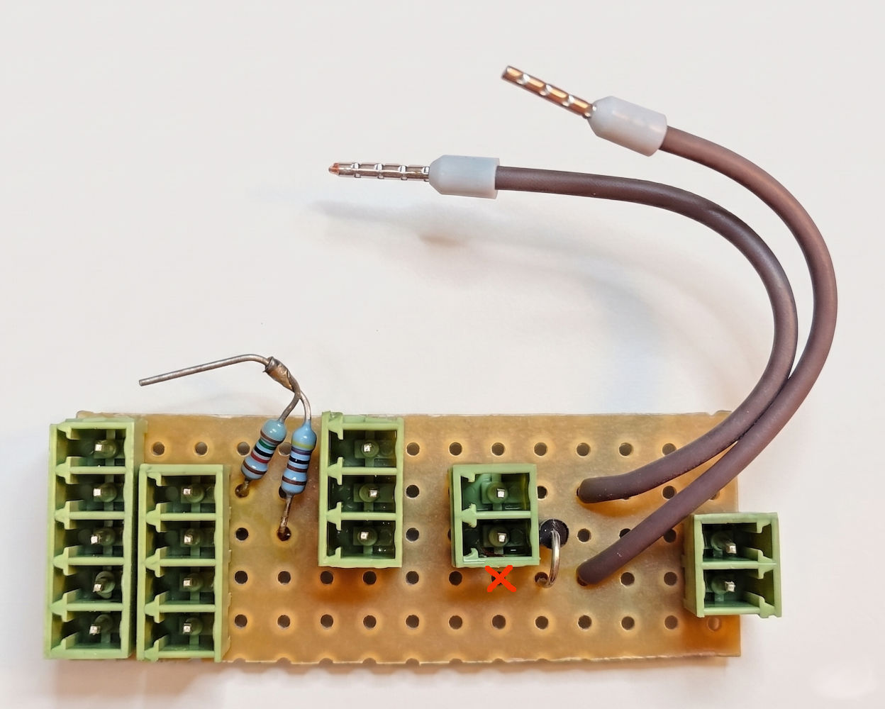 The completed Connection Board.
Board revisions from May 2026 have a 3-pin connector for the DC-DC voltage converter, to enable easier replacement of the voltage converter board should that fail.
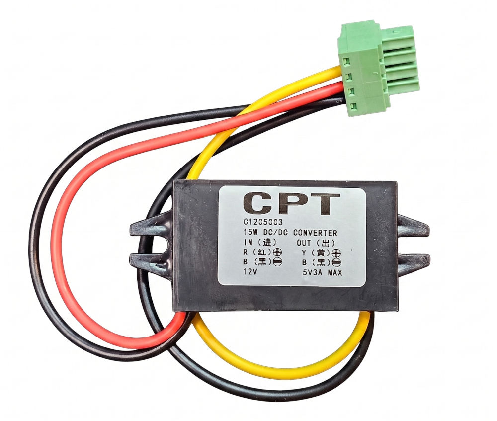 DC-DC voltage converter (with 4-pin plug as no 3-pin plugs were available at the time - 4th pin is not connected or used)
Pinout (top to bottom):
- 5V (OUT)
- 12V (IN)
- GND
Bi-colour LED
For visual status feedback, use a bi-colour LED (CPC/Farnell part SC07647 suggested).
- Cabling: Black/Red/Green cable cut to 30cm.
- Resistor: 120R.
- Pinout (LED SC07647):
- Pin by flat edge: Red
- Centre pin: Ground
- Pin opposite flat edge: Green
Network Interface Setup (USR TCP-232)
Before the controller can communicate, the USR TCP-232 module itself must be configured with appropriate IP settings. This will also show you its MAC address.
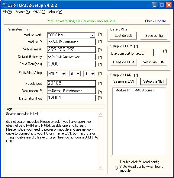 Example IP settings for the USR TCP-232 module. This interface is also where you can find the hardware MAC address of the network card.
Board configuration (MAC, Serial)
After assembly, you must configure the door controller via the console to match your hardware’s unique identifiers.
- Connect to the board via the serial console.
- Set the MAC address to match your network card:
set mac 00-FA-0F-AB-12-34 - Set the board serial number:
set serial 123
Enclosure & Front Cover
- LED Hole: Drill a 2mm hole using a template (approximately 18mm in from each edge).
- Finishing: File down the head of the LED for maximum light diffusion through the enclosure cover.
- Label: Apply the label to the top right corner of the enclosure, to the left of the LED hole.
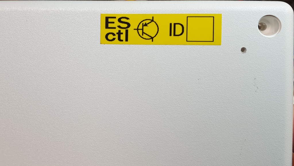 Positioning of the label on the front of the node, showing the hole for the status LED.
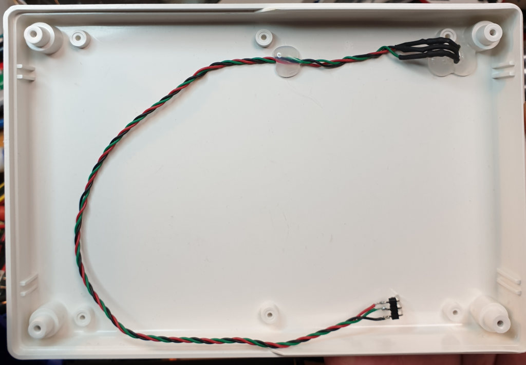 Positioning of the status LED inside the node cover.
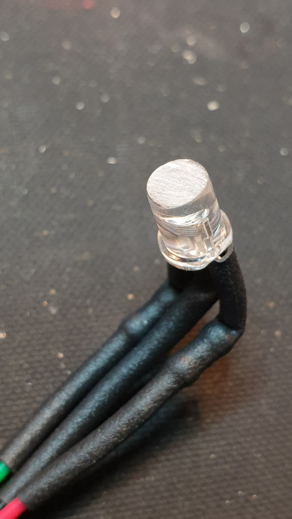 How to file down the head of the LED to ensure maximum light diffusion.